

![]()
![]()
![]()
![]()
Personal OBD2 Scan Tool Operation
 |
 |
 |
|
ISO
|
PWM
|
VPW
|
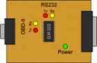
The indicator lights seen through the transparent cover of the Scan Tool hardware interface perform an important function by greatly simplifying the troubleshooting process. When you first connect the interface to the vehicle, the green "Power" LED should light up and the interface will perform a "Lamp Test" by sequentially lighting up the red and yellow LED's. If the green LED isn't on, check the OBD cable to make sure both ends are securely plugged in.
The RS232 indicator LEDs help troubleshoot problems with the serial connection. After connecting the ISO interface to your computer, and started up the software, you should see the RS-232 LEDs light up momentarily. If there is no activity, make sure the serial cable is securely plugged in, and that your COM port is properly configured.
The OBD2 bus activity LEDs help troubleshoot problems on the vehicle side. Before starting communication with the vehicle, ISO interface must first initialize the bus, and you should see the OBD Tx LED stay continuously lit for about five seconds. After that, if the software is not requesting any data from the interface, the chip will try to keep the bus 'alive' by sending 'dummy' messages to the ECU. In case there's no activity on the OBD2 bus, check that the ignition key is 'ON', then try to reset the interface by first unplugging the OBD2 cable and then plugging it back in.
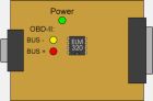
The indicator lights seen through the transparent cover of the Scan Tool hardware interface perform an important function by greatly simplifying the troubleshooting process. When you connect the interface to the vehicle, the green "Power" LED should light up. If the green LED isn't on, check the OBD2 cable to make sure both ends are securely plugged in.
The OBD2 bus activity LEDs help troubleshoot problems with the OBD2 bus. When you start the program, and go into "Sensors", the program will begin sending requests to the vehicle - you should see both the red and the yellow lights blink. If the lights stay lit, there is a problem with the cable (check the wiring), or the vehicle does not use the PWM protocol. If either or both of the lights stay dim, then the BUS- or BUS+ is shorted to ground (check wiring), or there is a problem with the serial connection.
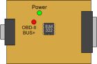
VPW Scan ToolThe indicator lights seen through the transparent cover of the Scan Tool hardware interface perform an important function by greatly simplifying the troubleshooting process. When you connect the interface to the vehicle, the green "Power" LED should light up. If the green LED isn't on, check the OBD2 cable to make sure both ends are securely plugged in.
The OBD2 bus activity LEDs help troubleshoot problems with the OBD2 bus. When you start the program, and go into "Sensors", the program will begin sending requests to the vehicle - you should see the red light blink. If the light stay lit, there is a problem with the cable (check the wiring), or the vehicle does not use the VPW protocol. If the light stays dim, then either the OBD2 Bus is shorted to ground (check wiring), or there is a problem with the serial connection.
BASIC TROUBLESHOOTINGIf you are having problems getting the Scan Tool to work, make sure that you have selected the correct serial port on the software screen. After you do this, close the program and restart the computer.
If after you turn on the ignition key (without starting the engine) you cannot read the stored diagnostic trouble codes (DTCs) or view the sensor values, it could be a hardware problem. Intermittent communication errors are sometimes caused by a bad OBD2 cable. This is especially true for PWM, where the data rate is four times higher than that of ISO or VPW. If you made your own cable, make sure it is less than six feet in length, and the pins are securely crimped onto the wire.
If the program reports "loss of connection", your vehicle may be using a different protocol, or is not compatible with OBD2. Check which pins are present inside the female J1962 connector (on the vehicle's side), and use the diagram below to help determine the protocol. If the vehicle is 1995 or older, look for an "OBD2 Certified" sticker under the hood.
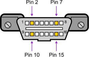
It is often possible to determine which protocol is used in a vehicle by looking at the diagnostic connection in the vehicle. The figure above shows the female diagnostic connector (DLC) in the vehicle. The table below shows how to determine the OBD2 protocol.
|
Pin
2
|
Pin
7
|
Pin
10
|
Pin
15
|
Protocol
|
|
must
have
|
-
|
must
have
|
-
|
PWM
|
|
must
have
|
-
|
-
|
-
|
VPW
|
|
-
|
must
have
|
-
|
may
have
|
ISO
|
In addition to pins 2, 7, 10 and 15, the connector should have pin 4 (chassis ground), 5 (signal ground) and 16 (battery positive). This means that for:
| PWM | The connector must have pins 2, 4, 5, 10 and 16. |
| VPW | The connector must have pins 2, 4, 5 and 16 but not 10 |
| ISO | The connector must have pins 4, 5, 7 and 16. Pin 15 may or may not be present. |
© Copyright 1999-2003 Innovationhouse.com. All Rights Reserved.